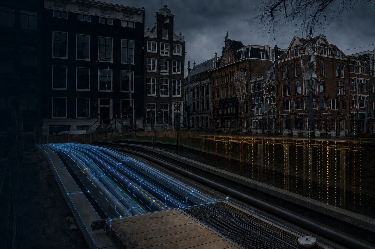
Draw a route or a crossing; it becomes a ground model you can defend — every figure back to its source and its standard.
Engineering runs across three of ORB’s domains — the ground, the networks in it, and what stands on it. Same engine, three subjects.

HDD and trenchless boring. Two points become a calculated drilling profile — bend radii checked against pipe strength, entry/exit, soil resistance and water crossings — an independent, verifiable bore plan the executing contractor cannot self-certify. This is ORB Drilling in use; the numbers below are the ones on screen, each with its source.
Not a picture of a bore: the model itself. Press play to run the pilot bore, the ream and the pullback through the measured soil layers — stress, mud pressure and vibration move with the bit. Drag to rotate.
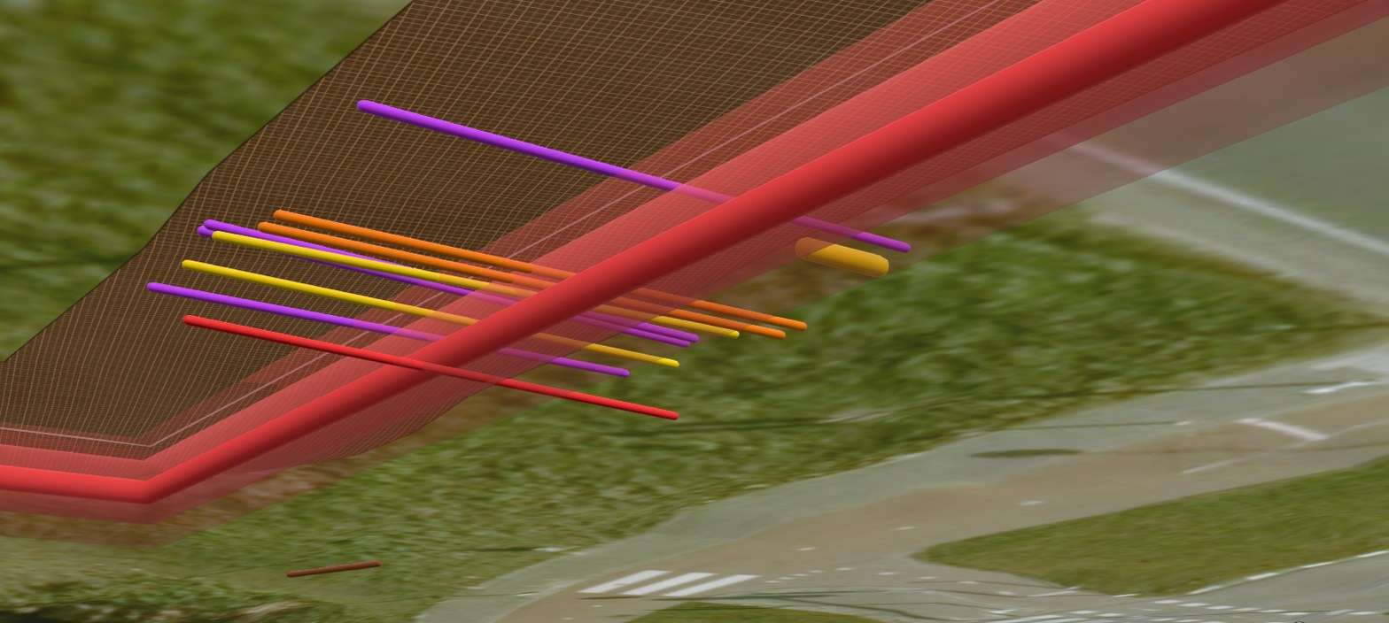
Cable & pipe routing (K&L). A drawn tracé becomes a peelable 3D ground model — soil bands from the subsurface model, cable & pipe lines at depth, a realistic open trench or trenchless bore. And the ground is rarely empty: ORB inventories every line in the working strip and gives it a risk class, 1–4, with the measure it calls for.
And those risk classes are not just labels — they are weights. ORB turns the working strip into a graph and runs a least-cost route (Dijkstra) across it: the line that steers around the class-4 zones, minimises crossings, and holds cover and bend radius within norm. Not the shortest line on a map — the cheapest defensible one through the ground that is actually there.

Design and assessment — for what stands on the ground. New foundations: pile bearing, negative skin friction, settlement and drivability, from a pseudo-CPT off GeoTOP (Koppejan, NEN 9997-1). Existing wooden piles: groundwater against the pile head, rot risk, toward a foundation label — the same measured ground, no assumptions.
The pile carries the load — yet the soil keeps settling. Settlement, not bearing, governs the design.
Beneath the tracé and the bore sits a reasoning layer on the ground itself — it recognises from the cable & pipe register and judges against the standard, instead of assuming.
The same reality, delivered at the depth you need. A report from the engine can become a living model, then a dashboard, then your own system — the same truth, deepening. You land where the risk is low and climb when it pays.
A one-off answer: a tracé study or bore plan, every figure carrying its source, standard and margin. Low risk, project-based.
€ per planA durable asset: the ground model and route, reusable, that keeps living instead of dying as a PDF.
assetA living lens on the engine — you design, check and produce the deliverable yourself. Recurring access.
subscriptionYour own engine and lenses, deployed and under your control. The deepest, stickiest rung.
deployedThe reason a report from ORB is worth more than a PDF from a consultant: it comes off the same engine, so it can climb. And because every result is traceable, an independent bore plan holds up against the party that profits from the meters. See how every figure is substantiated → Evidence & Verification.
Engineering is proven on real projects — boring profiles, tracé models, quantities and reports. Every other lens runs on the same engine, entered wherever your question sits.
